
Controlling LEDs via the Raspberry Pico and Python coding
Lighting up coloured LEDs and light sensors via the Pico

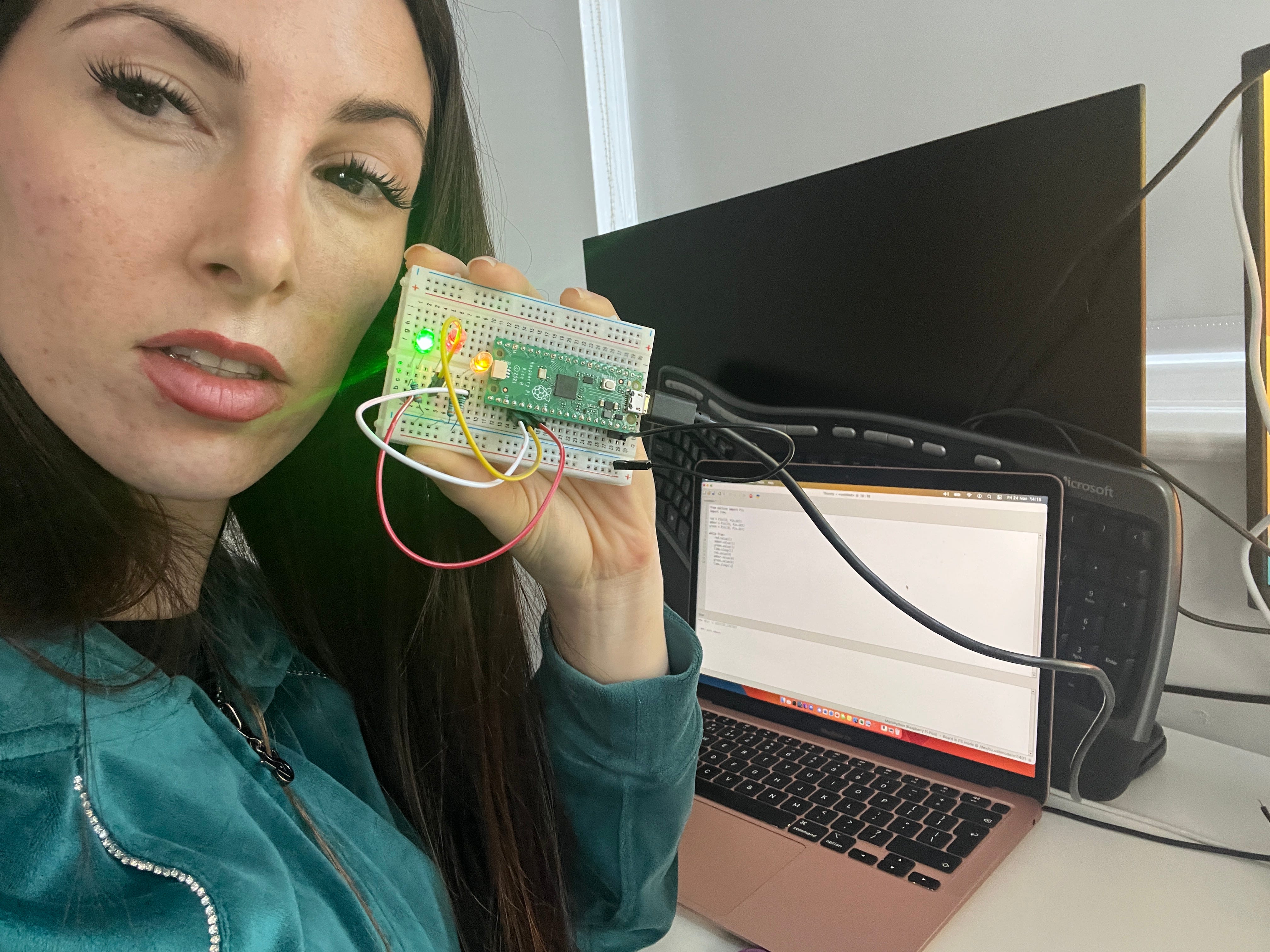
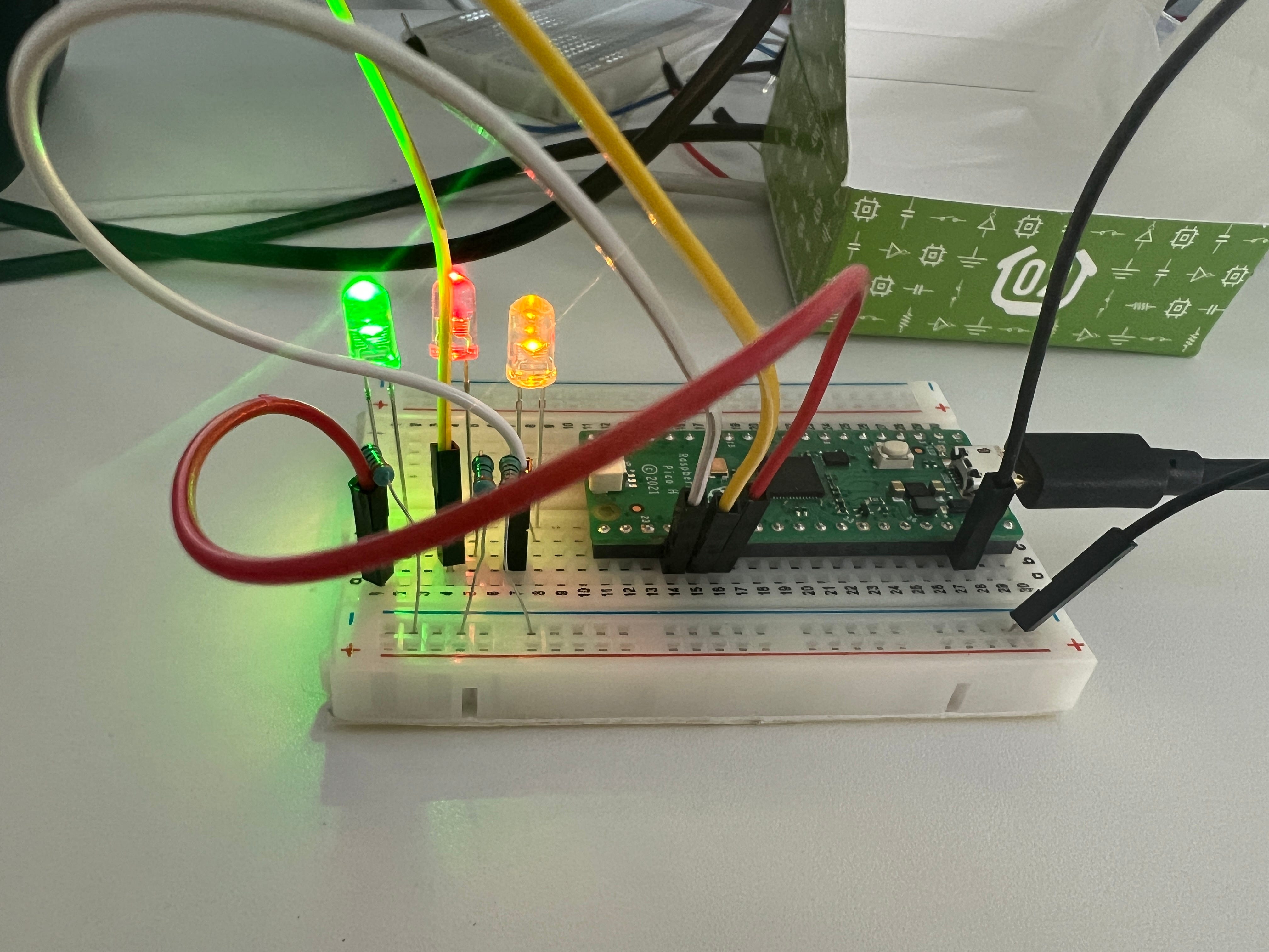
Light Emitting Diodes (LEDs) have a longer leg as the positive known as the Anode, the short leg is the Cathode. For the circuit the LED will need a 330 ohm resistor to limit the current drawn from the GPIO pins on each negative leg. Then all the negatives go into the ground pin on the Pico.
Connect the Anode of the LED to GPIO18, GPIO19, GPIO20. See map for Pico here.
Then just enter the following code:
from machine import Pin
import time
red = Pin(18, Pin.OUT)
amber = Pin(19, Pin.OUT)
green = Pin(20, Pin.OUT)
while True:
    red.value(1)
    amber.value(1)
    green.value(1)
    time.sleep(1)
    red.value(0)
    amber.value(0)
    green.value(0)
    time.sleep(1)
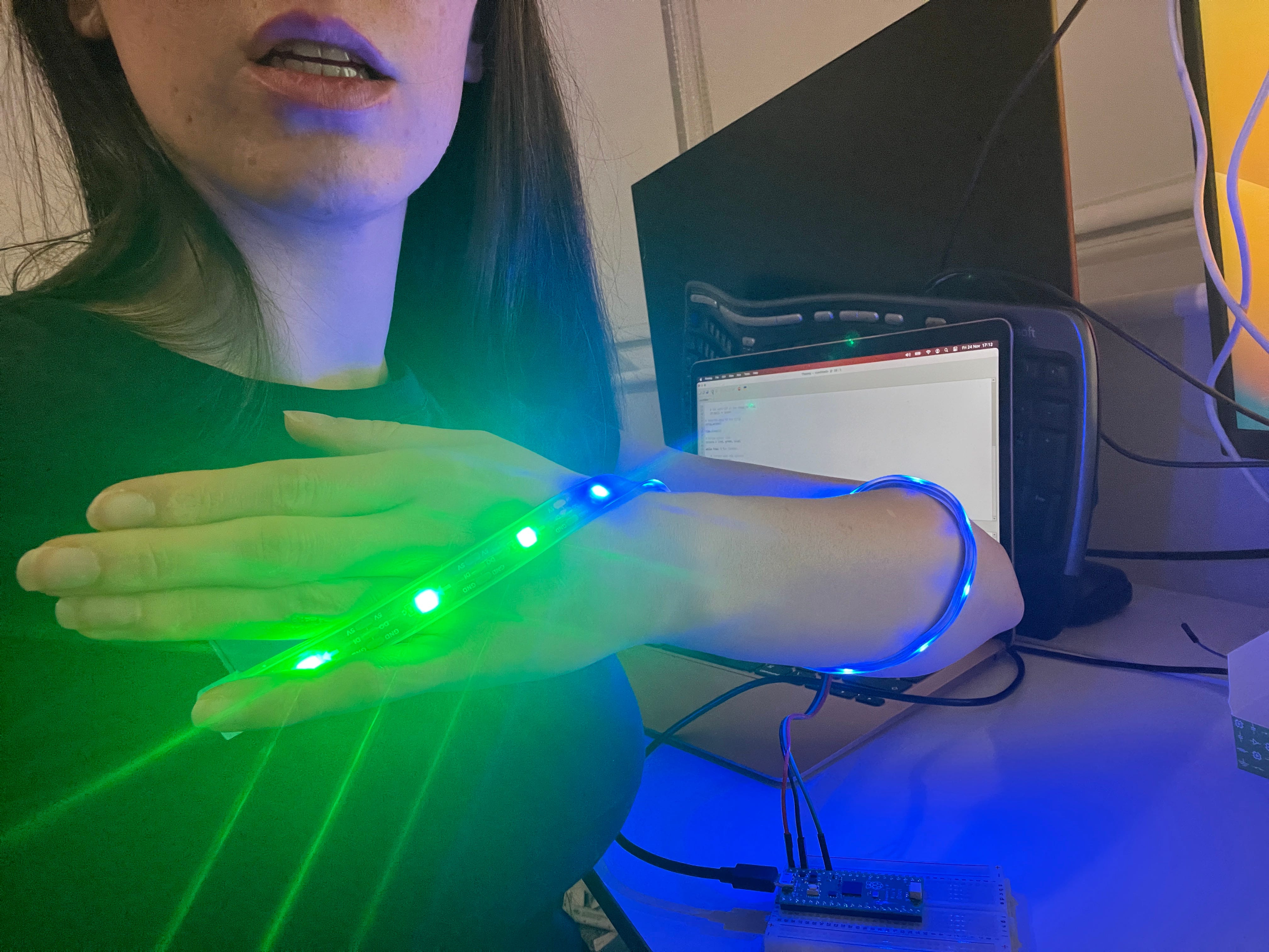
Lights in LED strips can be programmed individually, known as addressable LED. The LEDs in my strip are the WS2812 Addressable LEDs NeoPixels. They contain three small LEDs inside each, a red, green, and blue. These are mixed to create color. These LEDs have a controller chip inside that allow the code to address the individual LED by the microcontroller. RGB is a color system with each ranging in intensity from 0 to 255, giving over 16m values.
Powered via VBUS which provides 5V of power, the black into a GND pin, green into GPIO28.
In the code set the LED strip up, then set the PIN number, and the number of LEDs on the strip. Write the code then strip.write() to perform.
from machine import Pin
import time
from neopixel import NeoPixel
strip = NeoPixel(Pin(28),15)
strip[0] = (255,0,0)
strip[2] = (25,40,250)
strip[4] = (5,140,50)
strip[8] = (0,166,150)
strip.write()
time.sleep(2)

strip.fill((72,209,204))
strip.write()
time.sleep(2)
red = 255,0,0
green = 0,255,0
blue = 0,0,255
yellow = 255,255,0
pink = 255,20,147
for i in range(15):
    strip[i] = (pink)
strip.write()
time.sleep(2)
colours = [red, green, blue]
while True:
    for j in colours:
        for i in range(15):
            strip[i] = (j)
            time.sleep(0.1)
            strip.write()
And the result, this beautiful light of lights:
They are so flexible you could wear them as a wearable with some additional work!!!
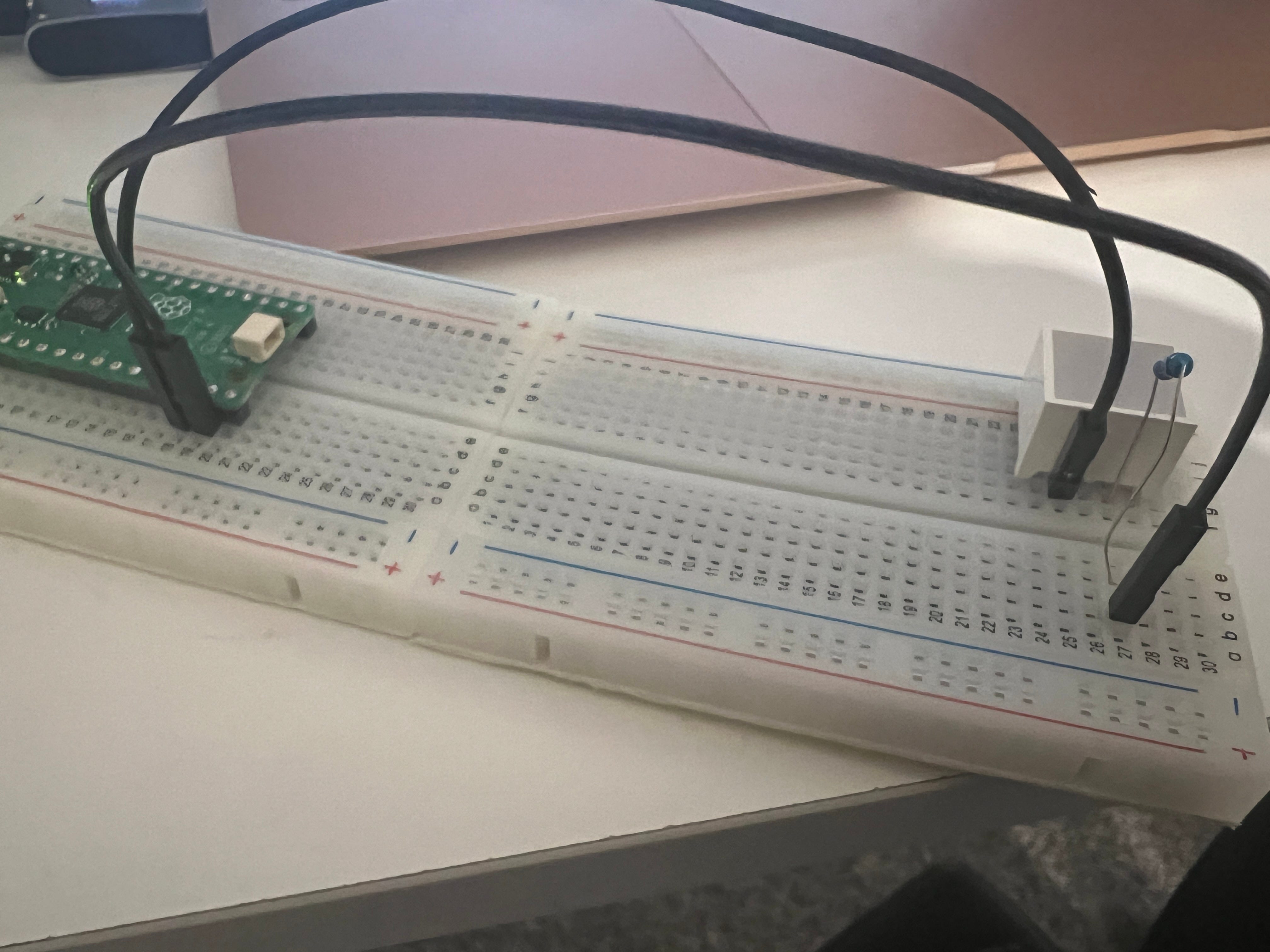
Next up we have the block LED light. Usually the longer leg is the positive (anode), current always flows from the positive to the negative. However, on this block LED the legs are the same size. As such the side with the text is the anode. Add a resistor between the positive and GPIO14 and then connect the negative up to GND pin.
from machine import Pin
green = Pin(25, Pin.OUT)
red = Pin(14, Pin.OUT)
green.value(1)
red.value(1)